
Constant Air Volume Dampers
SKP-LP
Low Pressure Constant Air Volume Dampers
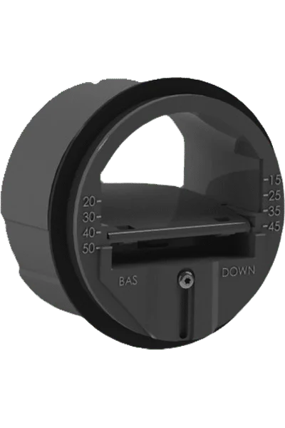
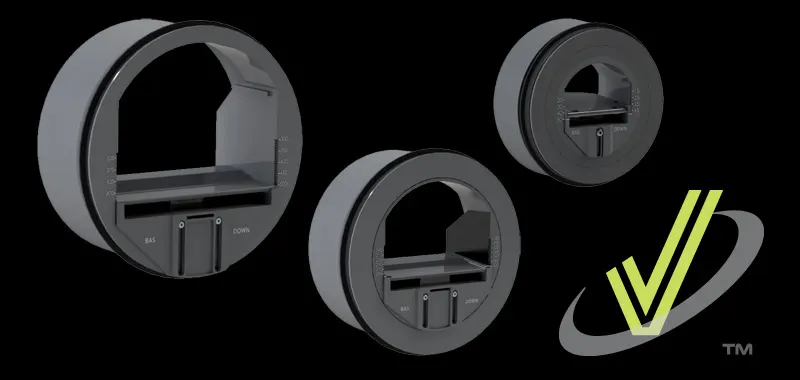
SKP-LP Low Pressure Constant Air Volume Dampers for circular duct greatly facilitate the balancing of ventilation systems. Those dampers maintain constant air volume within a pressure zone between 0.08 and 0.4 in.w.g. (20 – 100 Pa).
- Air volume preset by mean of a screw
- The damper will auto-adjust itself to maintain the desired volume of air while performing within the pressure range
- Housing is constructed from galvanized steel or plastic, the regulator blade is constructed from plastic and tightness joint from rubber
- Rated UL 2043
- Available for 4″, 5″, 6″, 8″ and 10″ diameter duct
- Material
- UL Rated Plastic
- Dimensions
- 10″ Duct, 100 mm, 125 mm, 150 mm, 160 mm, 200 mm, 250 mm, 4″ Duct, 5″ Duct, 6″ Duct, 8″ Duct, 80 mm
- Categories
- BalancingConstant Air Volume Dampers
Description
SKP-LP series Low Pressure Constant Air Volume Dampers (also called Constant Air Regulator) for circular duct greatly facilitate the balancing of ventilation systems. Those dampers maintain constant air volume within a pressure zone between 0.08 and 0.4 in.w.g. (20 – 100 Pa).
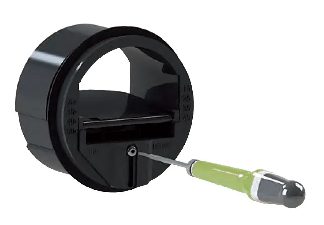
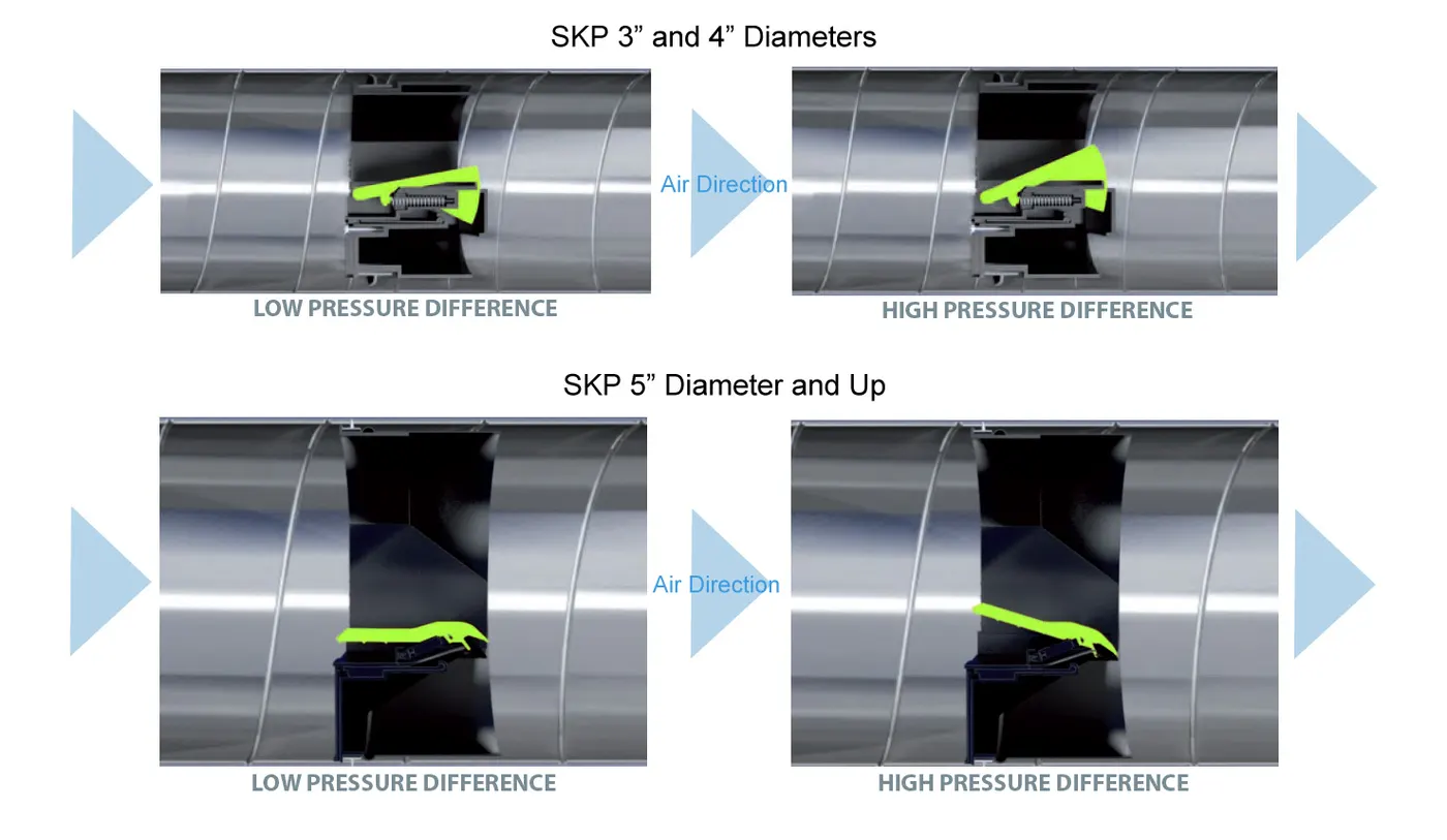
SKP-LP are self-adjustable dampers. They can be preset by the installer to maintain a specific air volume in cfm or m3/h, by mean of a screw. The damper will then auto-adjust itself to maintain the desired volume of air while performing within the pressure range. The damper is operated by an opposed opening force from a spring on the blade.
Housing is constructed from galvanized steel or plastic, the regulator blade is constructed from plastic and tightness joint from rubber. The entire product is rated UL 2043.
Specifications
23 37 XX – Air Balancing Dampers
SKP – Constant Air Volume Dampers/Regulators (Circular Duct)
Guide specification text for specifiers. The PDF is the reference document.
Read the specificationCollapse
PART 1 – GENERAL
1.1 SUMMARY
A. Section includes supply and installation of constant air volume (CAV) dampers/regulators for circular ducts, self-adjustable to maintain preset airflow despite pressure variations.
B. Provide one of the following models as scheduled:
- SKP (Standard): operates between 0.2 and 1.0 in.w.g. (50–250 Pa).
- SKP-LP (Low Pressure): operates between 0.08 and 0.4 in.w.g. (20–100 Pa).
- SKP-HP (High Pressure): operates between 0.6 and 2.4 in.w.g. (150–600 Pa).
C. Sizes: available for duct diameters ranging between 3 in and 10 in (as scheduled).
D. Purpose: facilitates air balancing; helps ensure optimal performance over time; suitable for high ceilings and areas difficult to access for balancing.
E. Operation: self-adjustable; preset by installer to maintain a specific airflow using a Torx No. 10 screwdriver; damper then automatically adjusts to maintain the set airflow within the applicable pressure range.
F. Construction: housing constructed from galvanized steel or plastic; regulator blade constructed from plastic; tightness joint from rubber; product rated UL 2043.
1.2 SUBMITTALS
A. Product Data: Manufacturer’s data for each scheduled model and size, including: pressure operating range, available airflow ranges by size/model, and acoustic power data.
B. Shop Drawings: Show model designation (SKP / SKP-LP / SKP-HP), duct diameter, installed length, airflow direction marking/orientation, and installation location(s).
C. Balancing/Commissioning Notes: Indicate target airflow setpoint(s) and corresponding adjustment setting(s) for each installed unit; include any required verification procedure.
1.3 QUALITY ASSURANCE
A. Provide damper/regulator(s) from a single manufacturer.
1.4 SUBSTITUTIONS
A. Substitutions per Division 01.
B. Proposed equals shall document compliance with: self-adjusting constant airflow function, specified pressure ranges for each model, available duct diameter range, and UL 2043 rating.
PART 2 – PRODUCTS
2.1 BASIS OF DESIGN
A. EffectiV SKP Series constant air volume damper/regulator for circular ducts.
2.2 MATERIALS AND CONSTRUCTION
A. Housing: galvanized steel or plastic, as provided by manufacturer for the scheduled model/size.
B. Regulator blade: plastic.
C. Tightness joint: rubber.
D. Mechanism: opposed opening force of an air blade against a spring; self-adjusts to maintain preset airflow.
E. Adjustment: Torx No. 10 locking/setting mechanism with graduated setpoint markings.
2.3 MODELS, SIZES, AND PERFORMANCE (AS SCHEDULED)
A. Model pressure ranges:
- SKP (Standard): 0.2–1.0 in.w.g. (50–250 Pa).
- SKP-LP (Low Pressure): 0.08–0.4 in.w.g. (20–100 Pa).
- SKP-HP (High Pressure): 0.6–2.4 in.w.g. (150–600 Pa).
B. Duct diameters: 3 in through 10 in, as scheduled.
C. Airflow setting ranges depend on model and diameter; provide units with airflow range covering the scheduled setpoint(s), per manufacturer published data.
D. Acoustics: provide acoustic power data per manufacturer published curves/tables for the scheduled model/diameter and operating pressure.
PART 3 – EXECUTION
3.1 EXAMINATION
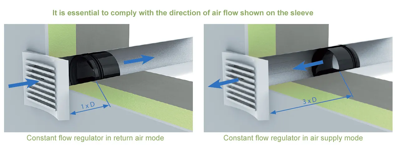
A. Verify duct diameter, installation location, airflow direction, and access for setting/verification prior to installation.
3.2 INSTALLATION
A. Install in circular ductwork in accordance with manufacturer instructions.
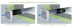
B. Comply with the airflow direction shown on the sleeve/body marking; install in the correct orientation for supply or return as scheduled.
3.3 ADJUSTING AND COMMISSIONING
A. Preset airflow setpoint using Torx No. 10 method and setpoint markings.
B. Tighten locking screw after setting.
C. Verify airflow under representative operating conditions.
Browse the family
Constant Air Volume Dampers
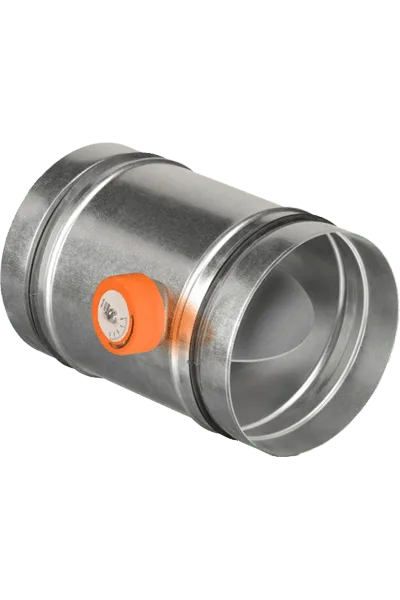
SKC-C
Constant Air Volume Damper For Circular Duct - High Pressure
Galvanized Steel · 10″ Duct, 12″ Duct, 16″ Duct, 4″ Duct, 5″ Duct, 6″ Duct, 8″ Duct
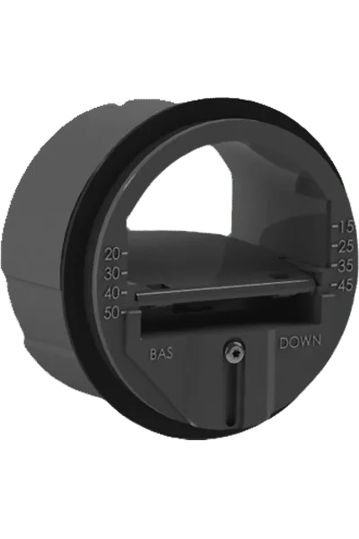
SKP
Low Pressure Constant Air Volume Dampers
UL Rated Plastic · 10″ Duct, 100 mm, 125 mm, 150 mm, 160 mm, 200 mm, 250 mm, 4″ Duct, 5″ Duct, 6″ Duct, 8″ Duct, 80 mm
SKP-HP
Low Pressure Constant Air Volume Dampers
UL Rated Plastic · 10″ Duct, 100 mm, 125 mm, 150 mm, 160 mm, 200 mm, 250 mm, 4″ Duct, 5″ Duct, 6″ Duct, 8″ Duct, 80 mm
SelectiV · Verified
Designing a room? Start with the air.
Use SelectiV to lay out diffusers in 3D, or ask for a Verified CFD study to validate comfort, IAQ and energy before anything is installed.