Architectural Duct Diffusers★ featured
BREEZ
Architectural Perforated Duct Diffusers
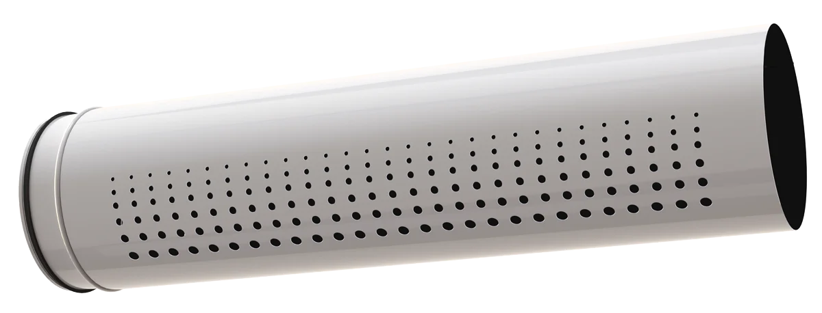
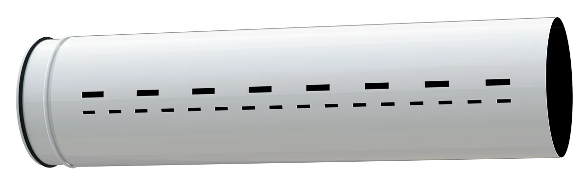
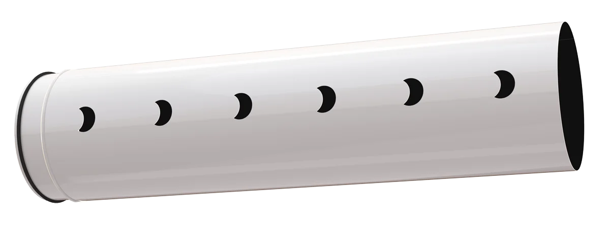
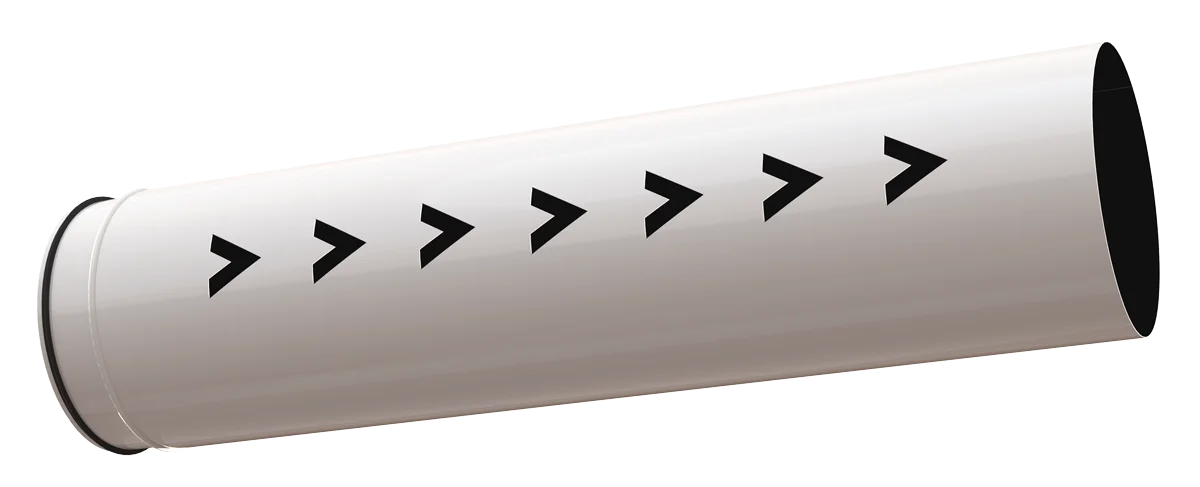
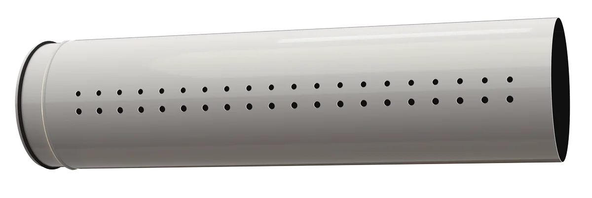
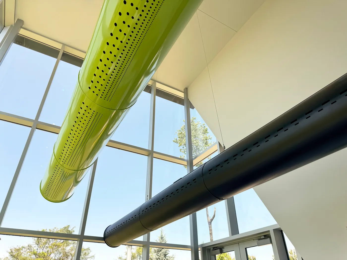

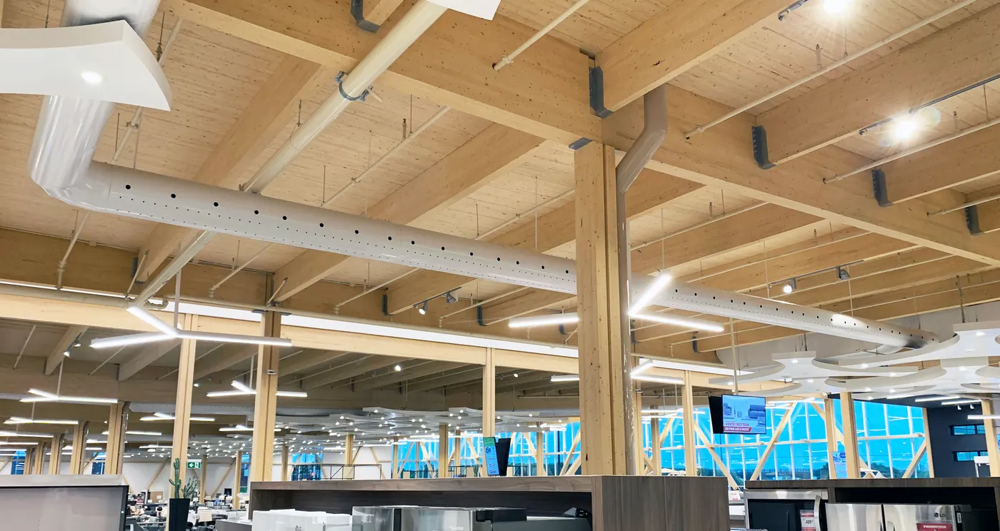
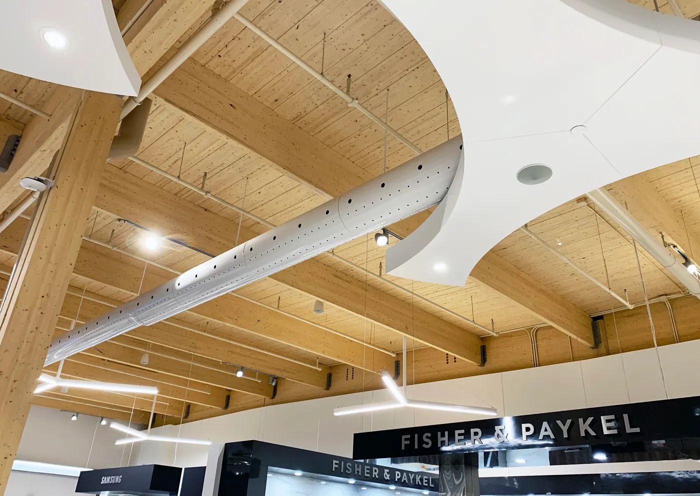

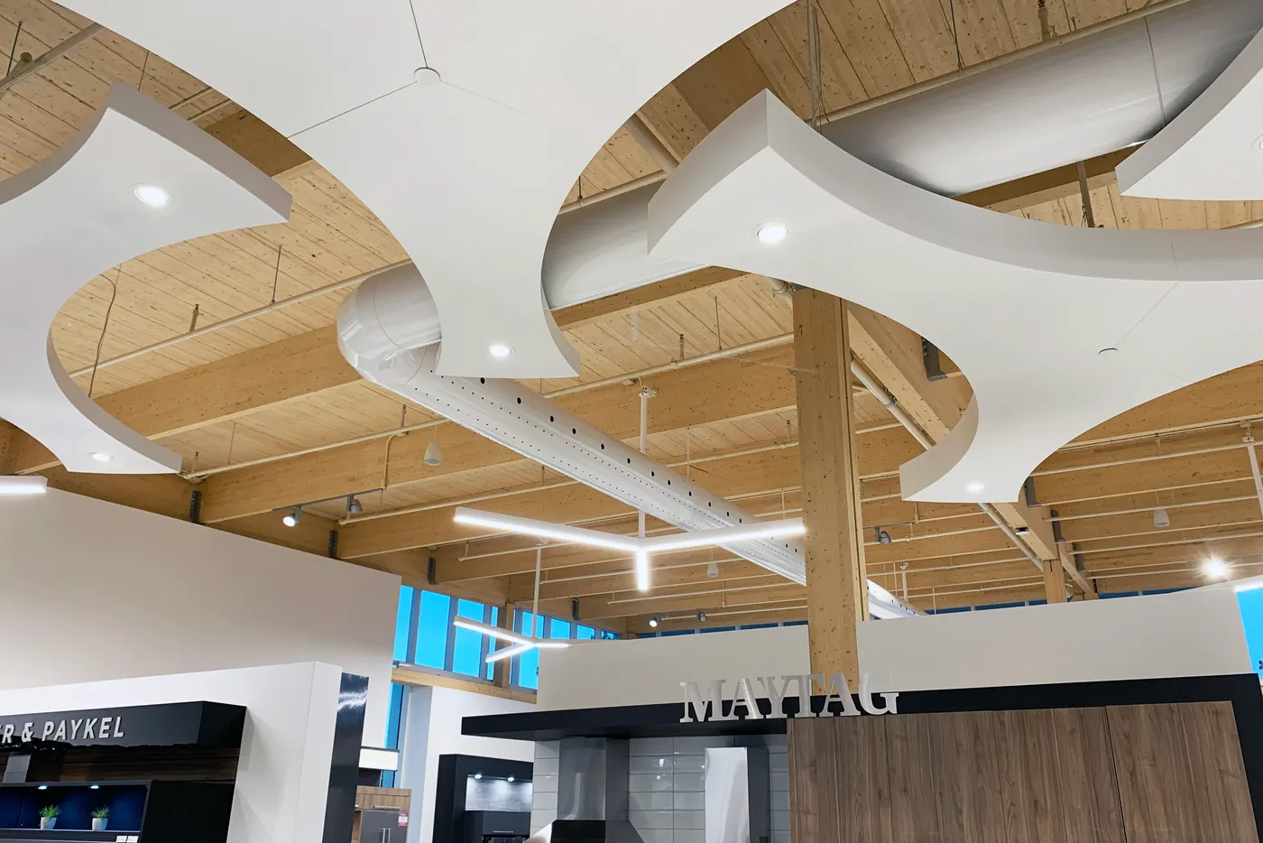
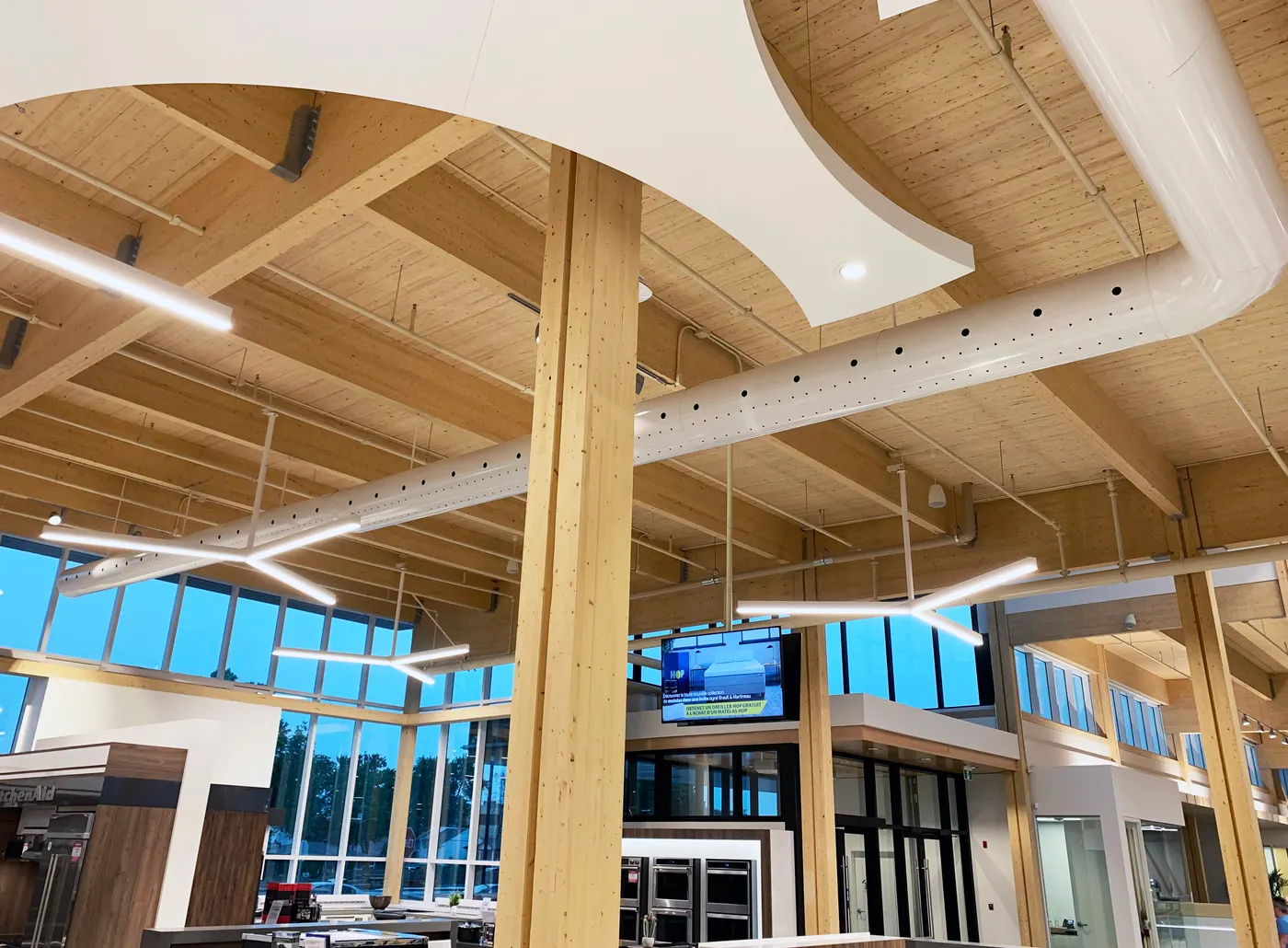

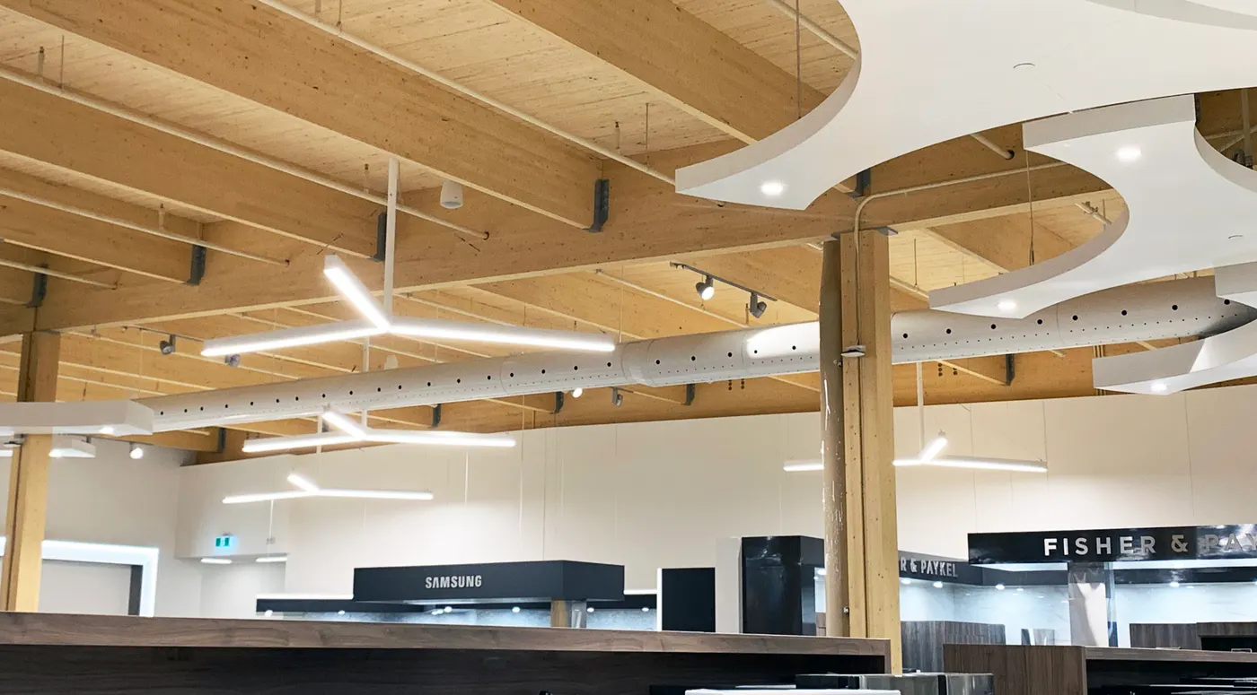
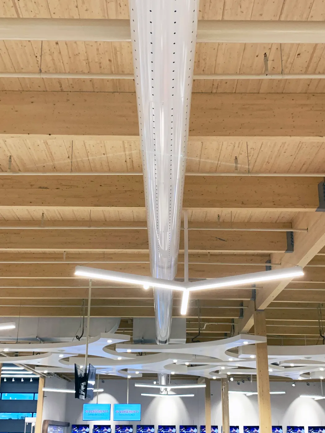
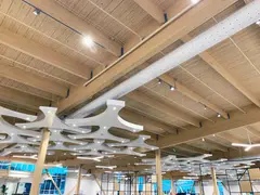
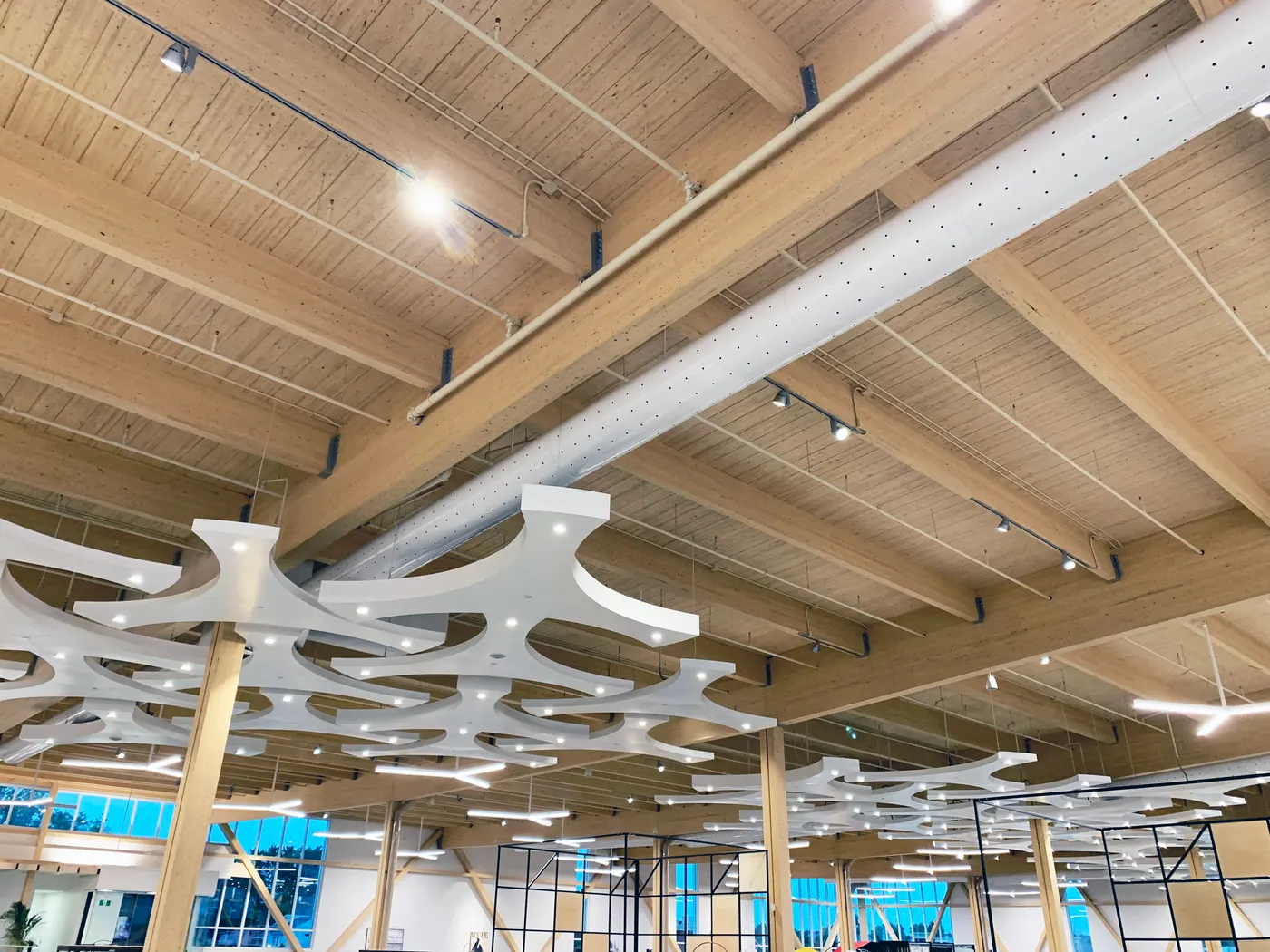

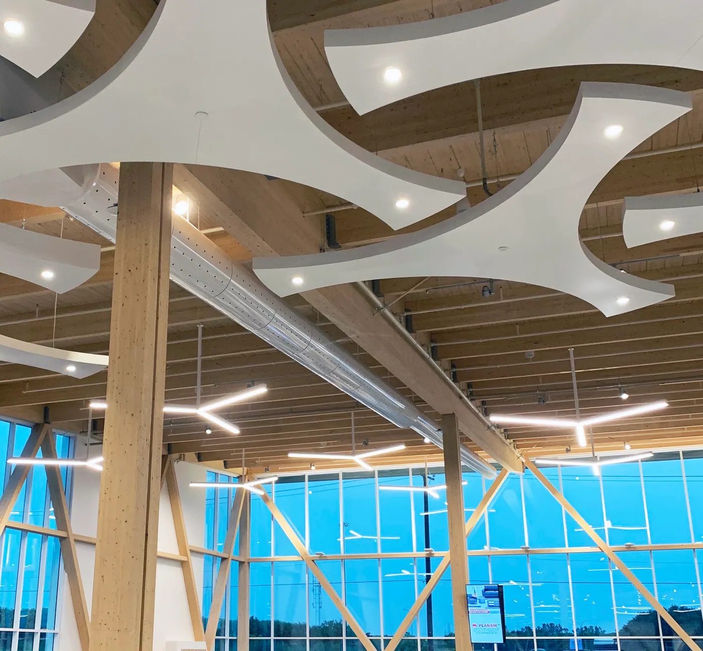

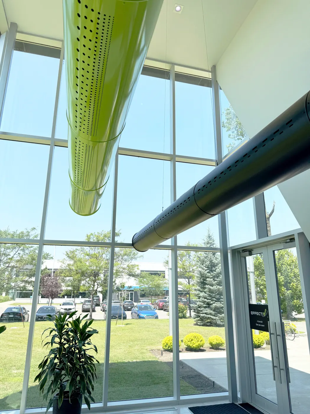

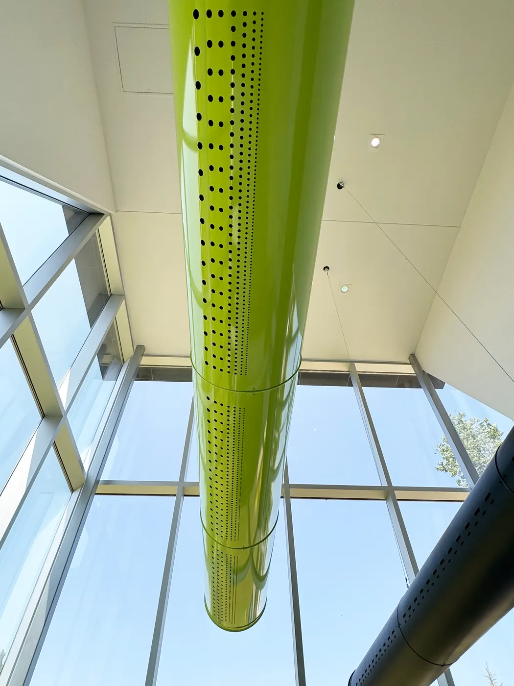
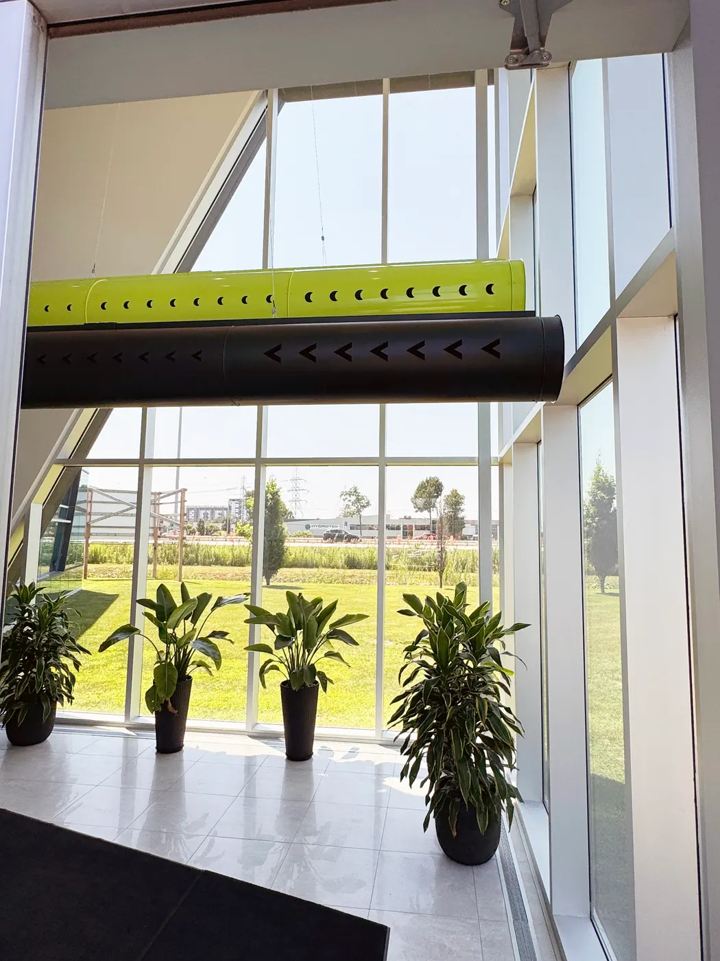
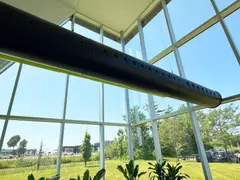
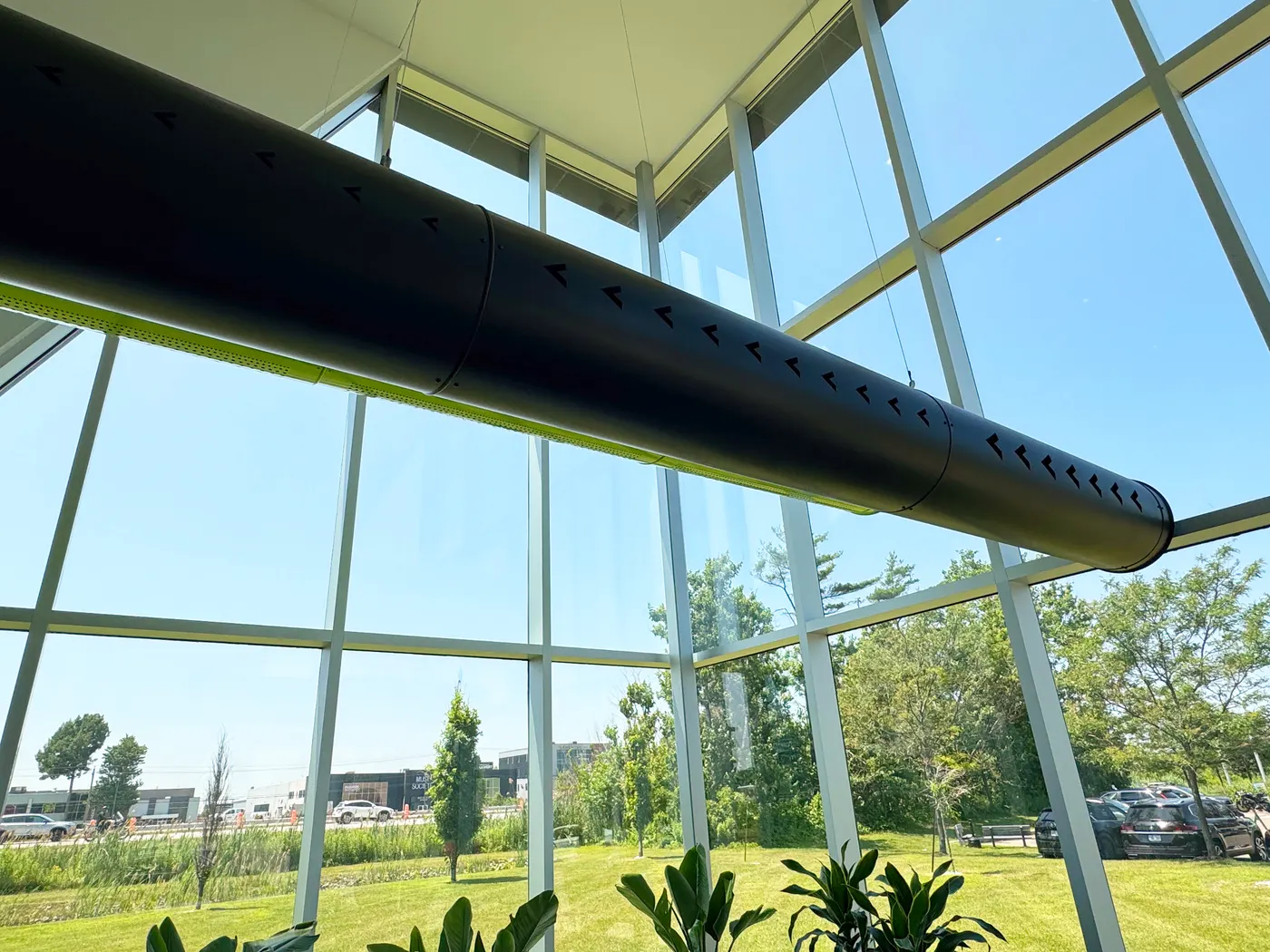
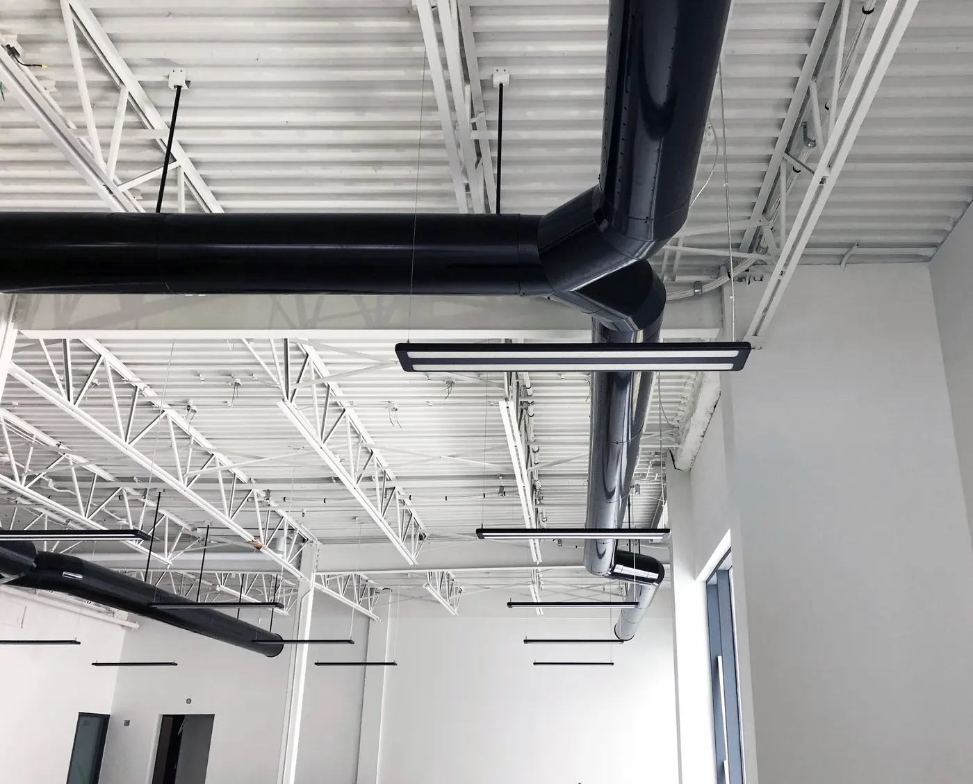
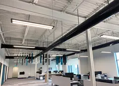
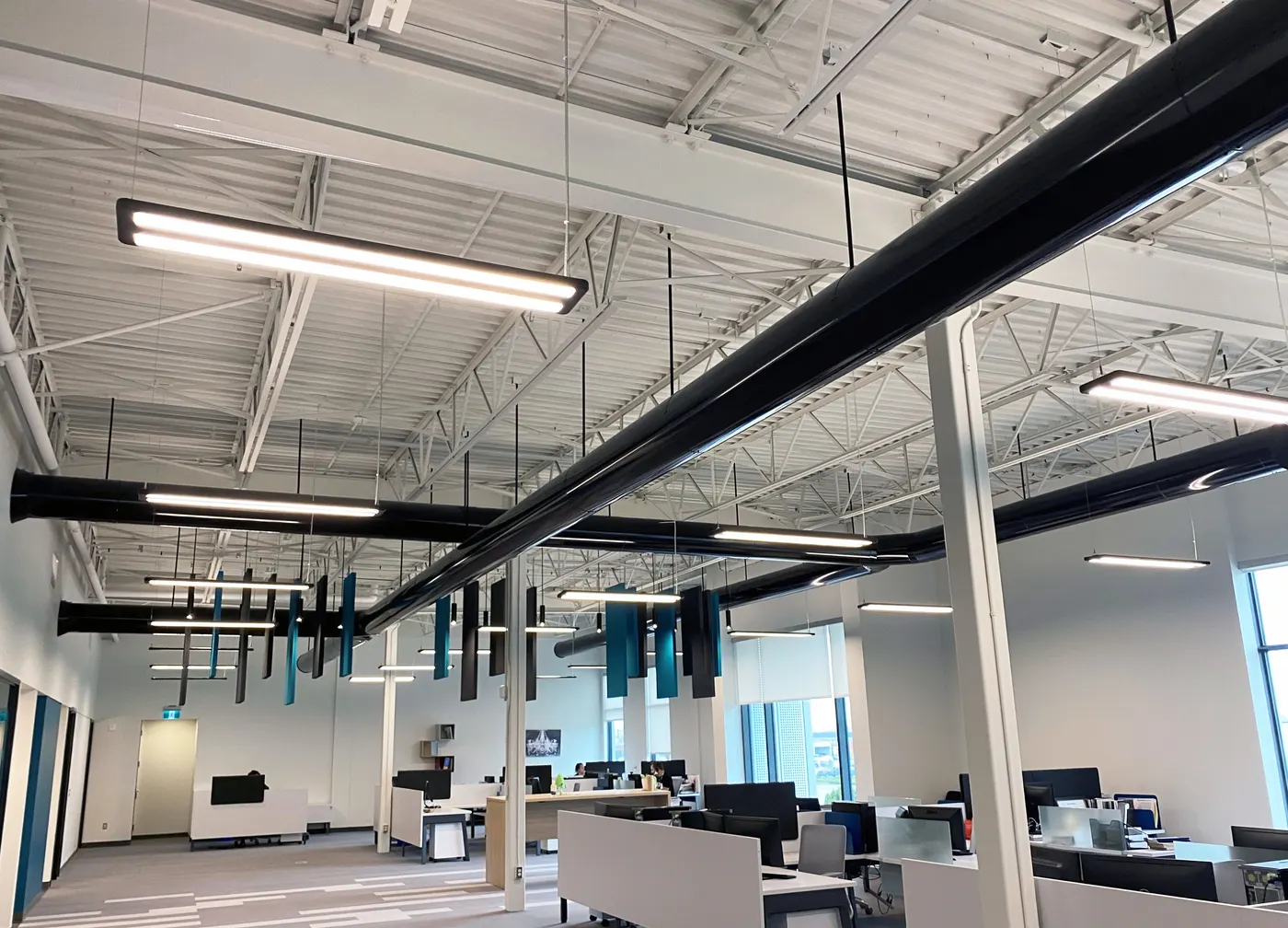

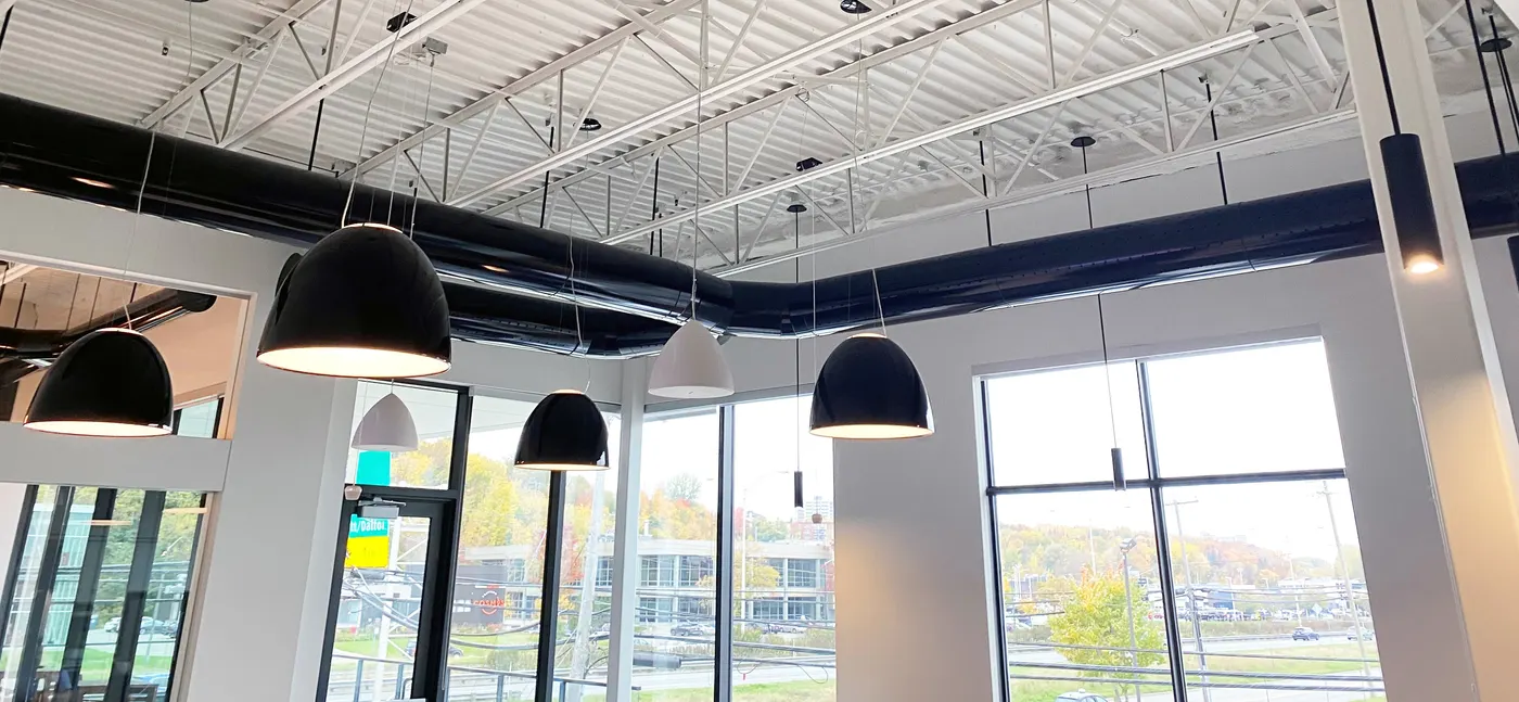

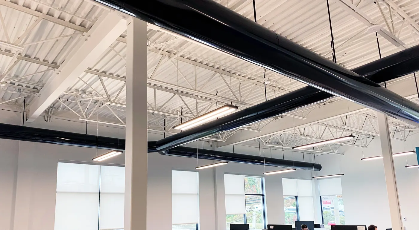
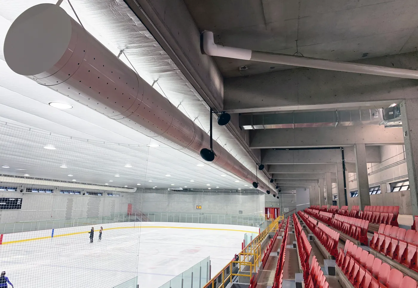

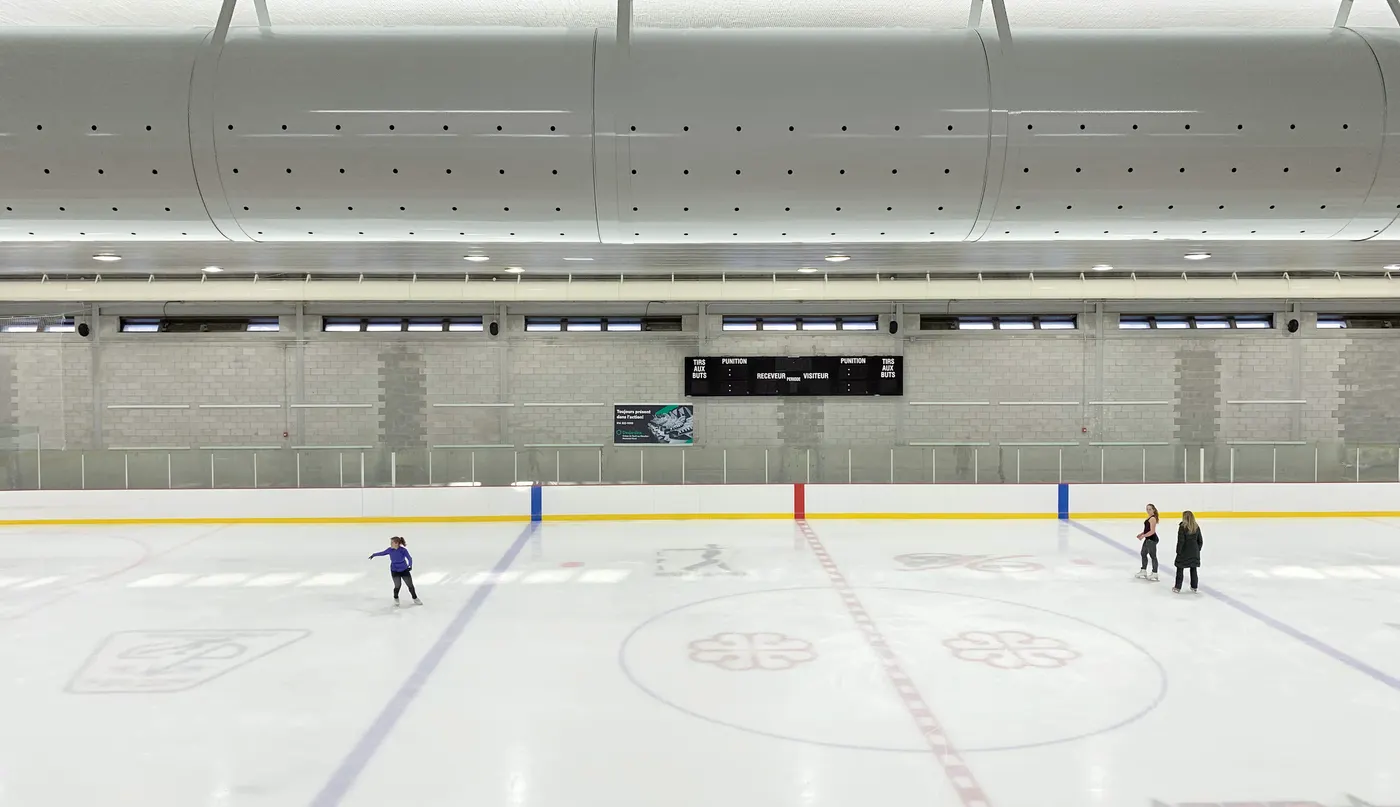
BREEZ represents EffectiV’s philosophy: architectural products built on measurable air-distribution high performance.
BREEZ series architectural perforated duct diffusers are designed for heating, cooling, and ventilation applications in spaces with ceiling heights from 16 to 60 feet. Suitable for both commercial and industrial environments, BREEZ combines a continuous, architectural appearance with engineered air distribution.
Unlike typical perforated spiral duct used in open-ceiling concepts, BREEZ is developed to meet both aesthetic and performance requirements. Designers can specify powder-coat colors and perforation patterns to integrate the duct line cleanly into the surrounding architecture.
For engineers, BREEZ offers flexible design options supported by SelectiV performance modeling and clear project documentation. Engineered high induction jet patterns promote effective air mixing and occupant comfort while maintaining low sound levels and good indoor air quality across large and complex spaces.
Downloads
Description
- Seamless continuous architectural duct line
- Engineered airflow using advanced performance simulations
- Low static pressure – high efficiency product
- Precision laser-cut perforations; multiple patterns available
- Pattern options: Circular, Rectangular, Arrow, Moon
- Perforation patterns optimized for any room geometry and operating conditions
- Custom powder-coat colors (architect-specified)
- Suspension or wall-mount configurations
- Commercial and industrial applications
- Recommended for 16–60 ft ceilings
- 5 ft long sections, available in 8” – 70” diameters
- Available with a wide range of duct fittings
Specifications
23 37 XX – Architectural Duct Diffusers
BREEZ – Architectural Perforated Duct Diffusers
Guide specification text for specifiers. The PDF is the reference document.
Read the specificationCollapse
PART 1 – GENERAL
1.1 SUMMARY
A. Section includes architectural perforated duct diffuser assemblies, including active (perforated) duct diffuser sections and passive (non-perforated) duct sections, with related fittings and mounting accessories.
1.2 SUBMITTALS
A. Product Data: Manufacturer’s catalog data for each product specified, including available diameters, section lengths, mounting configurations, finishes, perforation patterns, and mounting system options.
B. Shop Drawings: Dimensioned drawings showing duct diameters, section lengths, locations of active/perforated and passive sections, joints, fittings, supports, installation details, airflow orientation, and mounting system details.
C. Airflow Prediction Report (Required): Submit manufacturer-generated room airflow prediction report for each active duct-diffuser section and unique room condition, based on manufacturer performance data and recognized air-jet/room-airflow correction methods (including ΔT correction factors, Coanda effects, buoyancy effects, jet interaction, and wall/floor/ceiling collision effects). Report shall include:
- 3D room layout with diffuser placement.
- Predicted airflow visualization views: plan (top), section (side), and elevation (front).
- Throw distances for terminal velocities of 150, 100, 60, 50, 40, 30, and 20 fpm.
- Detailed pressure loss analysis at scheduled airflow, including calculation details for each duct section and each duct component.
- NC at scheduled airflow.
- Perceived NC: sound pressure at room center (5 ft height) from all sources combined across 63–8000 Hz octave bands; include resulting NC and key assumptions used.
D. Verified CFD Validation (When Indicated): Provide EffectiV Verified airflow CFD validation and summary report for spaces indicated on drawings and/or when diffuser operation is outside manufacturer published selection limits (airflow, ΔT, mounting height, geometry). Include boundary conditions and results plots supporting compliance with specified air distribution and acoustic criteria.
1.3 QUALITY ASSURANCE
A. Manufacturer Qualifications: Single manufacturer responsible for duct diffuser sections and related fittings/accessories to ensure consistent appearance, fit, and finish.
1.4 SUBSTITUTIONS
A. Substitutions shall comply with Division 01 substitution procedures.
B. Substitution Compliance Matrix (Required): Proposed “equal” products shall submit a line- by-line matrix demonstrating compliance with all requirements of Part 2 and all required submittals in 1.2, including Airflow Prediction Report deliverables. Deviations shall be clearly identified. Substitutions lacking complete documentation shall be rejected.
PART 2 – PRODUCTS
2.1 BASIS OF DESIGN
A. Basis of Design: EffectiV BREEZ Series Architectural Perforated Duct Diffusers (active perforated sections and passive sections), including fittings and mounting accessories by same manufacturer.
2.2 DIMENSIONS AND CONFIGURATION
A. Recommended for spaces with ceiling heights 16 to 60 ft.
B. Provide duct sections in 5 ft (60 in) lengths unless otherwise indicated.
C. Available duct diameters: 8 in to 70 in.
D. Mounting: Provide as scheduled for suspension or wall-mount configurations, complete with required accessories. Provide one of the following mounting systems as scheduled:
- Suspension rail system: Powder-coated mounting rails compatible with threaded rod suspension, including all required hardware and attachment points.
- Threaded rod cover system: Powder-coated cover(s) for threaded rods (to conceal rods for architectural exposed installations), where scheduled.
- Wall-mount bracket system: Wall-mount brackets for supporting duct diffuser assemblies from structure/walls, where scheduled.
2.3 MATERIALS AND CONSTRUCTION
A. Provide duct diffuser sections, passive duct sections, and fittings constructed of metal suitable for architectural exposed installation.
B. End Connections (Required): All duct sections and fittings shall be provided with male and female ends, or with a factory pre-installed junction sleeve, to facilitate alignment and installation and to provide consistent joint fit.
C. Jointing and Sealing: Fabrication, reinforcement, joints, and sealing shall comply with SMACNA HVAC Duct Construction Standards – Metal and Flexible (ANSI/SMACNA 006-2020). Where leakage classification or leakage testing is specified, criteria and procedures shall comply with ANSI/SMACNA 016-2012 (HVAC Air Duct Leakage Test Manual).
D. Perforations: Precision laser-cut perforation pattern as scheduled. Provide patterns as scheduled from the manufacturer’s available pattern set (circular, rectangular, crescent, arrow, etc.).
E. Dampers: Provide integral volume damper where scheduled.
2.4 FINISHES
A. Powder Coat: All exposed duct diffuser sections, fittings, and accessories shall be factory powder coated.
B. TGIC-Free Requirement: Powder coat shall be TGIC-free (e.g., HAA polyester TGIC-free chemistry or approved equal).
C. Color: As scheduled by Architect (RAL).
D. Fasteners: Provide self-tapping screws required for joining sections, powder coated to match duct color.
2.5 IDENTIFICATION AND ORIENTATION
A. Section Identification: Each BREEZ duct section shall be permanently and clearly identified to correlate with plans and installation drawings (unique section mark/ID).
B. Airflow Orientation Marking: Each active/perforated BREEZ duct section shall be clearly marked with airflow orientation to ensure correct installation.
2.6 PERFORMANCE REQUIREMENTS
A. Select perforation pattern and configuration using manufacturer selection/reporting tools to meet scheduled airflow, pressure loss, acoustics, and room-air distribution requirements.
B. Provide scheduled performance documentation consistent with Part 1 submittals (throw, pressure loss, NC, and Perceived NC).
PART 3 – EXECUTION
3.1 EXAMINATION
A. Verify field conditions, dimensions, and coordination with structure, ceiling systems, lighting, sprinklers, and other architectural elements before installation.
3.2 INSTALLATION
A. Install duct diffuser assemblies level, straight, and continuous in appearance; align joints and patterns.
B. Assemble joints using manufacturer-provided male/female ends or junction sleeves; secure sections using the matching powder-coated self-tapping screws specified.
C. Install each section per its identification mark and airflow orientation marking.
D. Install supports and accessories as required for the scheduled configuration, including the specified mounting system (suspension rails and/or threaded rod covers, or wall-mount brackets).
3.3 ADJUSTING AND CLEANING
A. Set dampers where provided to achieve scheduled airflow.
B. Clean exposed surfaces and remove protective coverings; repair or replace damaged finishes.
SelectiV · Verified
Designing a room? Start with the air.
Use SelectiV to lay out diffusers in 3D, or ask for a Verified CFD study to validate comfort, IAQ and energy before anything is installed.