KOBE★ featured
KOBE
Long Throw Adjustable Linear Jet Diffuser
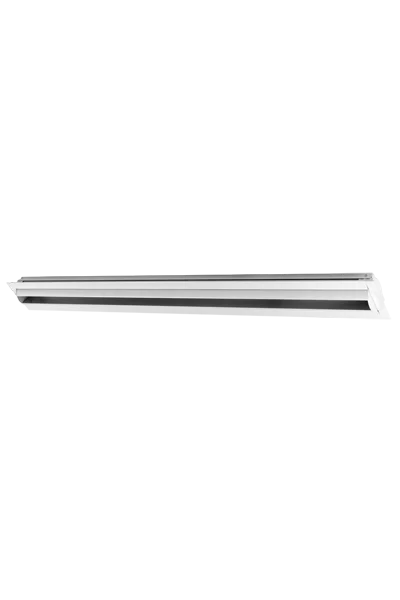


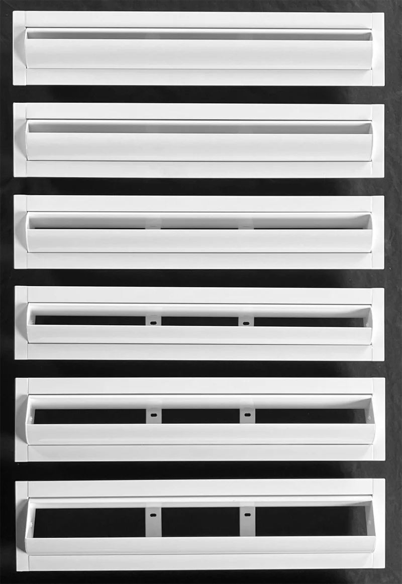

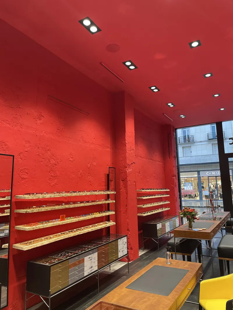

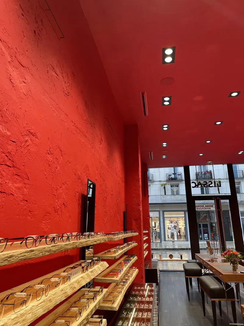
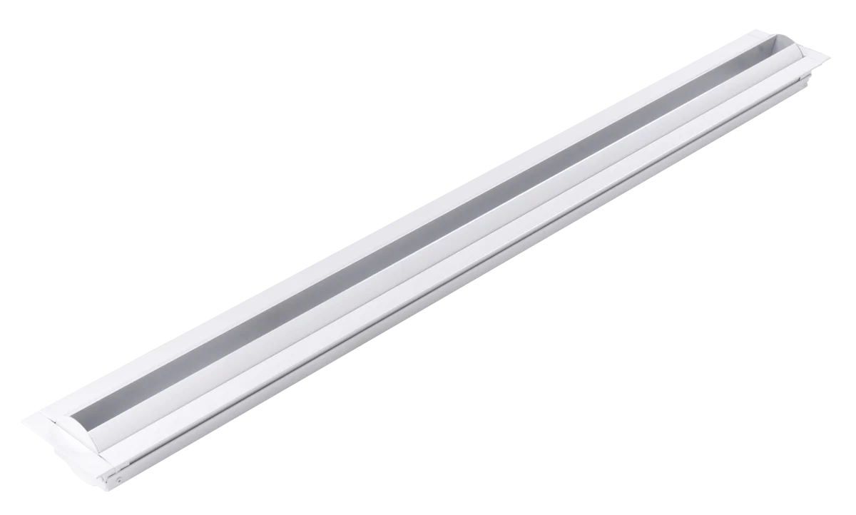
KOBE Long Throw Adjustable Linear Jet Diffusers have been designed to combine aesthetics with technical performance.
They can be mounted on the wall to diffuse the air horizontally in large spaces, or the ceiling to diffuse the air downward, for instance to cover high windowed walls.
With various slot sizes available and an adjustable supply angle of ± 30º, KOBE diffusers are suitable for all types of architectures and airflow requirements.
KOBE Long Throw Adjustable Linear Jet Diffusers are ideal for installation in large spaces such as shopping centers, airports, stations, sports halls, etc.
- Adjustable long throw, ideal for large rooms or high ceilings
- Ideal solution to push air downwards and to cover windowed walls
- Six different slot widths to answer requirements for a wide range of air volumes
- Architecturally appealing linear diffuser
- Easy clip mounting system available with PLKB plenum
- Made in aluminium
Downloads
Description
KOBE diffusers work with a high induction rate that minimizes stratification in large spaces. They can operate with a temperature differential of up to 22ºF (12ºC) and provide optimum performance with both variable and constant air flow.
Specifications
23 37 XX – High Performance Architectural Linear Jet Diffusers
KOBE – Adjustable Long Throw Linear Jet Diffusers (with PLKB plenums)
Guide specification text for specifiers. The PDF is the reference document.
Read the specificationCollapse
PART 1 – GENERAL
1.1 SUMMARY
A. Adjustable long-throw linear jet diffuser(s) for large spaces and high ceilings; suitable for wall mounting (horizontal long-throw) or ceiling mounting (downward wash, including window walls).
B. Field-adjustable discharge angle: ±30 degrees.
C. Suitable for variable or constant airflow; temperature differential up to 22°F (12°C).
D. Continuous appearance: Where a continuous linear appearance is indicated, install individual KOBE diffusers flange-to-flange to form a continuous line.
1.2 SUBMITTALS
A. Product Data: Manufacturer’s data for scheduled slot width(s), length(s), and mounting type(s), including pressure loss, diffuser-generated NC, and throws (including values with and without Coanda effect, where published).
B. Shop Drawings: Show diffuser model designation, slot width, nominal length, finish, mounting type, plenum type (if provided), duct connection layout, and all scheduled damper/equalizer and accessory selections. Where continuous appearance is required, indicate flange-to-flange layout and joint locations.
C. Airflow Prediction Report (Required): Provide manufacturer-generated room airflow prediction report for each diffuser type and unique room condition using manufacturer performance data and recognized correction methods. Report shall include:
- 3D room layout with diffuser placement.
- Predicted airflow visualization views: plan (top), section (side), elevation (front).
- Throw distances for terminal velocities of 150, 100, 60, 50, 40, 30, and 20 fpm.
- Pressure loss at scheduled airflow.
- Diffuser-generated NC.
- Perceived NC at room center (5 ft height), 63–8000 Hz octave bands; include assumptions used.
D. Verified CFD Validation (When Indicated): Provide EffectiV Verified CFD validation and summary report for spaces indicated on drawings and/or when operation is outside published selection limits.
1.3 SUBSTITUTIONS
A. Substitutions per Division 01.
B. Proposed equals shall provide a line-by-line compliance matrix including all Part 1 deliverables, including the Airflow Prediction Report.
PART 2 – PRODUCTS
2.1 BASIS OF DESIGN
A. EffectiV KOBE adjustable long-throw linear jet diffuser(s), aluminum construction.
2.2 SLOT WIDTHS (AS SCHEDULED)
A. Provide one of the following slot widths as scheduled: 15, 20, 25, 30, 40, or 50 mm.
2.3 LENGTHS (AS SCHEDULED)
A. Provide nominal lengths as scheduled, within the published nominal length range 300 to 2000 mm.
2.4 MATERIALS AND FINISH
A. Construction: Aluminum.
B. Finish: Factory powder coat, TGIC-free, White M9016 (RAL 9016) unless otherwise scheduled; alternate RAL finishes where specified.
2.5 MOUNTING (AS SCHEDULED)
A. Provide one of the following mounting systems as scheduled:
- -PM: Concealed bracket mounting.
- -PL: Concealed spring clips mounting (clip system available with PLKB plenum).
2.6 PLENUMS AND INTEGRATED AIR VOLUME DAMPERS (AS SCHEDULED)
A. Plenum (as scheduled): Provide PLKB plenum compatible with selected mounting type.
B. Plenum types (as scheduled):
- PLKB-S-PM
- PLKB-S-PL
- PLKB-T-PM
- PLKB-T-PL
C. Integrated air volume damper / equalizer options (as scheduled): Perforated damper + air equalizer; R; MRT; MRT2; EB; EB2.
PART 3 – EXECUTION
3.1 INSTALLATION
A. Install diffusers level, straight, and aligned; coordinate wall or ceiling mounting orientation and discharge direction per plans.
B. Where continuous appearance is required, install units flange-to-flange with tight, aligned joints.
C. Set discharge angle within ±30° range as required for the design intent.
3.2 ADJUSTING
A. Balance to scheduled airflow and verify discharge direction and long-throw performance.
SelectiV · Verified
Designing a room? Start with the air.
Use SelectiV to lay out diffusers in 3D, or ask for a Verified CFD study to validate comfort, IAQ and energy before anything is installed.